Principle and data - MAXcomputer GmbH - www.max-computer.de


Main menu:
Principle and data
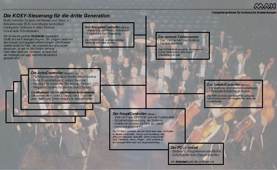
An orchestra served as a model (see picture), there are many paralleles concerning the cooperation, furthermore, this comparison has helped a lot during the development. Perhaps it is helpful for the beginner and for the service-man to understand the controller, too.
The conception for the future must base on modern modules and make use of their technical possibilities. Let us present you our new Multi-Controller conception:
Fast and modern 32bit Master - Many ports and interfaces, flexible on a separate board. Functions for security and administration. Flash-Routines for master and slaves to update the firmware when extended.
BusSystem for internal communication - Enough slots for future extensions. Up to 8 slaves can be integrated, the software for multiple-axes-operation is and will be developed accordingly.
Independent slaves with performance endstep - Up-to-date 8bit-Controllers as AxisControllers with Intelligence on-site. Output stage for the motor control up to 2,5 A. For bigger currents an external output stage is used.
Flexible energy supply - Power supply, transformator and distribution for small and big performances.
A big technical progress especially in the following points:
Microstepping for smooth operation and "soft" movements
High feed speeds through modern and helpful software modules
Short machining times through "fluid" movements
Extended range of applications through a big number of possibles axles
The software is and remains the familiar CAD/CAM-programme with direct machine control nccad, which will be delivered together with the MCS from version 7.5 upward in different types. The manual operation window of this version shows some noteworthy functions:
More than 4 axes.
Enlargened and extended position display with free colour selection (fore-/ background).
Switch of the manual operation mode (continuous, as before or in jumps of 3 different widths).
Switch of the setting mode for the WZP with/without correction of the radius.
Switch of the manual operation to handwheel or JoyStick via key.
Many relays, with fields for free names.
Direct input of the analogue control tension with free name.
Direct speed- and rotation-direction-control of the machining unit (if you have one of the kind) with direct input of rpm. In this case, it is not necessary to convert control tension into revs.

Flexible number of axles
Integration of electronic handwheelsEach main ais can have an optional handwheel. Its handling is just optimal for a mechanic - he can work as usual, in good old tradition.
Axis control via JoyStickA very comfortable alternative as option, e.g. for quick TeachIn-Programming.
Way-Measuring system for the main axesDifferent methods can be integrated optionally. The AxisControllers get the relating intelligence. You need to consult us for this choice, clear ideas about accuracy and resolution are important
Selection of the communication portRS232 (COM resp. serial) or USB are available. On customer's request, a CAN-linkage can be realized. Selection of the ports and connections for future extensionsThey can be integrated at once, to prevent costs for sending back and forth. If you e.g. intend to equip your control with handwheels later, you should order cables and sockets for it with your first order. Updating the FirmwareAll used controllers are flashable - also on-site by the means of the PC-Software.
Compose your own individual controller. Don't hesitate to contact us. We would like to advise you.
Date: 1 June 2006, subject to alterations
* Only when upgrade-set MCSA1 is ordered
The most important technical data of the MCS, in function blocks:
Hardware-Dimension
Ports to PC
- COM (RS232, serial port, 9pol Dsub)
- USB 2.0 (FullSpeed, Socket Type B)
Others on demand
Inputs Safety
Switch- Sensor for protection hood
Sensor for operational stateOutputs
3 Status indicators (LEDs - Attention, Free, Error)
1 analogue output with 2 different max. values*
Inputs
Depth controller/scanner*
tool-length measurer*
Key-matrix 4x4 for 16 keys*
3 analogue inputs for JoyStick*
2 analogue inputs for Override and similar*
Outputs
Stepping motor 2-phase max 2,5A/35 V
Clock frequency, direction and current, for external output stage
Inputs without optocoupler
5 for free use (handwheel etc)*
Inputs with optocouplers**
5 for free use
Other inputs
2 analogue ones (Override of the speed,etc)*
Microstep-operation
Linear interpolation
Ramp control
Real-time-override for feed
LookAhead or spooler for soft controur-control
Current reduction in standstill
4 current intensities to switch
Sensitive power and feed-control
8 digital in-/outputs accord. to application**
7 relays with switchcontacts 24V/1A*
1 Net-relay 230V/4A, 2-pin Off
BUS-board
OUtputs
Relays connections (25pin Dsub), compatible with KOSY2*
7 relays with change-over contact 24V/1A*
24V/0,5A resp. 10V/0,5A control voltage*
Plug-in connection for U-axis, compatible with KOSY2*
BUS-connections
3 pin bars 16pol, internal BUS-protocol
4 additional BUS-connections*
Power pack board
Voltage input
Net input: 230V/50Hz/approx. 200VA
Voltage outputs
35V/approx. 8A for small steppint motors
24V/max. 0,5A
5V/max. 0,3A
3,3V/max. 0,2A
230V/800W to program via relay 6
Sensor output
"Breakdown of operational voltage" **